Attempting to revive dead 260 AH LiFePO4 Cells
I now have both of Willie's 12V wooden power boxes containing mostly dead 260 AH LiFePO4 cells, plus a spare cell. The 4 cells in the box I got yesterday are all dead, reading only a few millivolts.
Since Scott Little and Willie had previously worked with a load of dead cells from the Escort, I looked at his messages, and here is what I found (so far):
Mar 31, 2018, 1:28 PM
Any suggestions?
----------
and Willie's reply:
No. I guess they are gone. Recently, we've been stressing over the
maintenance costs on the old 13 S85. Something like $8k in a few months
with only about $4k income. The Escort puts the Tesla in the shade. I
had around $40k in that car and put less than 200 miles on it. The
failed 260ah cells have had almost zero use. After I pulled them out of
the Escort, I left them several years with the miniBMS modules
installed. When I noticed the lights out on the modules, I finally
disconnected them. The modules are SUPPOSED to shutdown with zero drain
down around 2v. Now, that car and it's battery are without value.
Did you report that the cells remaining in the barn all have zero voltage?
Now, I need to apply myself to preserving the 48 cells in the Hyundai.
Last time I attempted to charge, a dead 12v thwarted me. That and
forgetting how things are supposed to work.
----------
Fri, Mar 16, 2018, 6:43 PM
If I connect the 5V supply to a hefty discharged
LiFePO4, it tries to deliver in excess of 60A to the cell. I got around
this problem with a small-value series R, a piece of 11ga galvanized
steel wire about 16” long. The charger is controlled
by a circuit I made which compares cell voltage to a reference
voltage. When cell voltage reaches 3.7 (or 3.3 if the switch is
thrown), the charger is turned off via a solid state relay. Yes, as
the cell approaches full charge the charger starts to go on
and off frequently but, eventually, the voltage gets high enough that
the charger stays off for a long time.
--------
Scott found this: http://www.powerstream.com/LLL
showing how to care for them.
Lithium iron phosphate is a type of lithium-ion battery, since the energy is stored in the same way, moving and storing lithium ions instead of lithium metal. These cells and batteries not only have high capacity, but can deliver high power. High-power lithium iron phosphate batteries are now a reality. They can be used as storage cells or power sources.
In addition, Lithium Iron Phosphate batteries are among the longest lived batteries ever developed. Test data in the laboratory show up to 2000 charge/discharge cycles. This is due to the extremely robust crystal structure of the iron phosphate, which does not break down under repeated packing and unpacking of the lithium ions during charging and discharging
 4. Four times higher energy density
than Lead-acid battery
4. Four times higher energy density
than Lead-acid battery
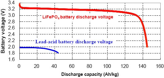
Lead-acid battery is an aqueous system. The single cell voltage is nominally 2V during discharge. Lead is a heavy metal, its specific capacity is only 44Ah/kg. In comparison, the lithium iron phosphate (LiFePO4) cell is a non-aqueous system, having 3.2V as its nominal voltage during discharge. Its specific capacity is more than 145Ah/kg. Therefore, the gravimetric energy density of LiFePO4 battery is 130Wh/kg, four times higher than that of Lead-
acid battery, 35Wh/kg.
5. Simplified battery management system and battery charger
Large overcharge tolerance and self-balance characteristic of LiFePO4 battery can simplify the battery protection and balance circuit boards, lowering their cost. The one step charging process allows the use of a simpler conventional power supplier to charge LiFePO4 battery instead of using an expensive professional Li-ion battery charger.
6. Longer cycle life
In comparison with LiCoO2 battery which has a cycle life of 400 cycles, LiFePO4 battery extends its cycle life up to 2000 cycles.
7. High temperature performance
is detrimental to have a LiCoO2 battery working at elevated temperature, such as 60°C. However, a LiFePO4 battery runs better at elevated temperature, offering 10% more capacity, due to higher lithium ionic conductivity.
End of cut and Paste from the Powerstream website.
More from Scott Little writing to Willie
Dec 6, 2017, 9:17 AM
---------
Since Scott Little and Willie had previously worked with a load of dead cells from the Escort, I looked at his messages, and here is what I found (so far):
Mar 31, 2018, 1:28 PM
| |||
I have not had good luck so far with the
super-dead 260’s…ones that have <0.01v initial voltage. I first
tried a 50A charge rate and that cell got up to 3.3 volts but hung there
and started to get hot instead of going up to 3.7. I disconnected
it and, by the next morning, the voltage was less than 1 volt just due
to self-discharge.
A second 260 was charged with a constant-current
supply set to 10A. After the voltage got above 3.0, I disconnected it
and observed a similar self-discharge rate. I then charged it again to
2.7 or 2.8 and disconnected it again. On the
third such cycle, the cell started off at around 2.0 volts and, after
all night charging at 10A, was _down_ to 1.8 volts in the morning! That cell appears to be getting worse inside as a result of my efforts.
----------
and Willie's reply:
No. I guess they are gone. Recently, we've been stressing over the
maintenance costs on the old 13 S85. Something like $8k in a few months
with only about $4k income. The Escort puts the Tesla in the shade. I
had around $40k in that car and put less than 200 miles on it. The
failed 260ah cells have had almost zero use. After I pulled them out of
the Escort, I left them several years with the miniBMS modules
installed. When I noticed the lights out on the modules, I finally
disconnected them. The modules are SUPPOSED to shutdown with zero drain
down around 2v. Now, that car and it's battery are without value.
Did you report that the cells remaining in the barn all have zero voltage?
Now, I need to apply myself to preserving the 48 cells in the Hyundai.
Last time I attempted to charge, a dead 12v thwarted me. That and
forgetting how things are supposed to work.
----------
Fri, Mar 16, 2018, 6:43 PM
| |||
5 more of your 260’s came back to your big
barn this afternoon, Willie. They all tested pretty good. Curiously,
they all came out around 230 Ah or 88.5% of nominal. That makes me
worry that something has gone wrong with my tester
but I haven’t changed anything….and I got a decent reading on my
high-quality 18650. I would be surprised if my tester is more than 5%
in error.
Anyway, that makes 11 tested 260’s now sitting on the bench there where I put the last tested cells.
BTW, I modified my 45A charger* so I can switch
between full charge….3.7 volts, which is what I use for the capacity
testing….and storage charge 3.3 volts. The 5 cells delivered today
were all charged back up to 3.3 volts after testing.
I surveyed the remaining 30 or so 260’s and found
very few with any voltage at all and only 2 with 3+ volts. I took the
5-pack that contained those 2 cells. The other 3 in that pack are near
zero volts. I’ll see if the dead ones can
be resurrected.
*the charger is a cheap Chinese 5v power supply that
was advertised to deliver 60A. When I got it, I tried drawing 60A from
it and it blew out a big wide trace on the circuit board. I repaired
the trace with a heavy Cu wire and that restored
operation. Recently, I must have loaded it near 60A again because a
second trace has melted. Clearly, the supply does not meet the
advertised performance.
--------
Scott found this: http://www.powerstream.com/LLL
showing how to care for them.
Lithium iron phosphate is a type of lithium-ion battery, since the energy is stored in the same way, moving and storing lithium ions instead of lithium metal. These cells and batteries not only have high capacity, but can deliver high power. High-power lithium iron phosphate batteries are now a reality. They can be used as storage cells or power sources.
In addition, Lithium Iron Phosphate batteries are among the longest lived batteries ever developed. Test data in the laboratory show up to 2000 charge/discharge cycles. This is due to the extremely robust crystal structure of the iron phosphate, which does not break down under repeated packing and unpacking of the lithium ions during charging and discharging
| Lithium Iron Phosphate Parameters | |||
| Nominal voltage | 3.2 Volts | ||
| Peak voltage | 3.65 Volts | Note our new data on capacity versus charge voltage | |
| Absolute Minimum discharge voltage | 2.0 Volts | ||
| CV charge voltage | 3.65 Volts | 100% charge | |
| CV charge voltage | 3.5 Volts | 95% charge | |
| Charge Temperature | 0°-40°C | ||
| Discharge Temperature | -10°-60°C |
| LiFePO4 Battery Charging | ||||||||
| Innovation in Li-ion Battery: LiFePO 4 Power Battery, Faster charging and safer performance
Although small capacity Li-ion (polymer) Battery
containing lithium cobalt oxide (LiCoO 2) offers a the best mass energy density
and volume energy density available, lithium cobalt oxide (LiCoO2) is very
expensive and unsafe for large scale Li-ion Batteries.
Recently lithium iron phosphate (LiFePO4) has been
becoming the "best-choice" of materials in commercial Li-ion (and polymer)
batteries for large capacity and high power applications, such as laptops,
power tools, wheel chairs, e-bikes, e-cars and e-buses.
The LiFePO4 battery has hybrid characters: it is as safe
as the lead-acid battery and as powerful as the lithium ion battery. The
advantages of large format Li-ion (and polymer) batteries containing lithium
iron phosphate (LiFePO4) are listed as below:
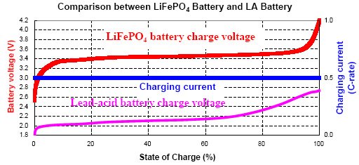
1. Conventional charging During the conventional lithium ion charging process, a conventional Li-ion Battery containing lithium iron phosphate (LiFePO4) needs two steps to be fully charged: step 1 uses constant current (CC) to reach about 60% State of Charge (SOC); step 2 takes place when charge voltage reaches 3.65V per cell, which is the upper limit of effective charging voltage. Turning from constant current (CC) to constant voltage (CV) means that the charge current is limited by what the battery will accept at that voltage, so the charging current tapers down asymptotically, just as a capacitor charged through a resistor will reach the final voltage asymptotically.
To put a clock to the process, step 1 (60% SOC) needs
about one hour and the step 2 (40% SOC) needs another two hours.
1. Fast "forced" charging: |
Because an overvoltage can be applied to the LiFePO4
battery without decomposing the electrolyte, it can be charged by only one step
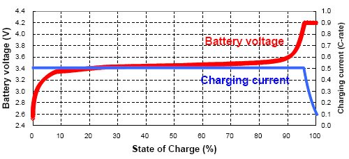
of CC to reach 95% SOC or be charged by CC+CV to get 100% SOC. This is similar
to the way lead acid batteries are safely force charged. The minimum total
charging time will be about two hours.
2. Large overcharge tolerance and safer performance
A LiCoO2 battery has a very narrow overcharge tolerance, about 0.1V over the 4.2V per cell charging voltage plateau, which also the upper limit of the charge voltage. Continuous charging over 4.3V would either damage the battery performance, such as cycle life, or result in fire or explosion.
A LiFePO4 battery has a much wider overcharge tolerance
of about 0.7V from its charging voltage plateau of 3.5V per cell. When measured
with a differential scanning calorimeter (DSC) the exothermic heat of the
chemical reaction with electrolyte after overcharge is only 90 Joules/gram for
LiFePO4 versus 1600 J/g for LiCoO2 . The greater the exothermic heat, the more
vigorous the fire or explosion that can happen when the battery is abused.
A LiFePO4 battery can be safely overcharged to 4.2 volts
per cell, but higher voltages will start to break down the organic
electrolytes. Nevertheless, it is common to charge a 12 volt a 4-cell series
pack with a lead acid battery charger. The maximum voltage of these chargers,
whether AC powered, or using a car's alternator, is 14.4 volts. This works
fine, but lead acid chargers will lower their voltage to 13.8 volts for the
float charge, and so will usually terminate before the LiFe pack is at 100%.
For this reason a special LiFe charger is required to reliably get to 100%
capacity.
Due to the added safety factor, these packs are
preferred for large capacity and high power applications. From the viewpoint of
large overcharge tolerance and safety performance, a LiFePO4 battery is similar
to a lead-acid battery.
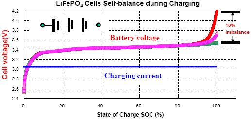
. Self balance
Unlike the lead-acid battery, a number of LiFePO4 cells in a battery pack in series connection cannot balance each other during charging process. This is because the charge current stops flowing when the cell is full. This is why the LiFEPO4 packs need management boards.
Unlike the lead-acid battery, a number of LiFePO4 cells in a battery pack in series connection cannot balance each other during charging process. This is because the charge current stops flowing when the cell is full. This is why the LiFEPO4 packs need management boards.
Lead-acid battery is an aqueous system. The single cell voltage is nominally 2V during discharge. Lead is a heavy metal, its specific capacity is only 44Ah/kg. In comparison, the lithium iron phosphate (LiFePO4) cell is a non-aqueous system, having 3.2V as its nominal voltage during discharge. Its specific capacity is more than 145Ah/kg. Therefore, the gravimetric energy density of LiFePO4 battery is 130Wh/kg, four times higher than that of Lead-
acid battery, 35Wh/kg.
5. Simplified battery management system and battery charger
Large overcharge tolerance and self-balance characteristic of LiFePO4 battery can simplify the battery protection and balance circuit boards, lowering their cost. The one step charging process allows the use of a simpler conventional power supplier to charge LiFePO4 battery instead of using an expensive professional Li-ion battery charger.
6. Longer cycle life
In comparison with LiCoO2 battery which has a cycle life of 400 cycles, LiFePO4 battery extends its cycle life up to 2000 cycles.
7. High temperature performance
is detrimental to have a LiCoO2 battery working at elevated temperature, such as 60°C. However, a LiFePO4 battery runs better at elevated temperature, offering 10% more capacity, due to higher lithium ionic conductivity.
More from Scott Little writing to Willie
Dec 6, 2017, 9:17 AM
"Please put one of them down on the pile of 260's. I'm about finished
testing the 5 I got recently (they all look good) and will be coming
down for more of them soon. It takes days to recharge one with the
6A charger I have. I am therefore embarking upon the construction
of a 50A single cell LFP charger using a dirt-simple design that will
monitor cell voltage and leave the charger on until V > 3.60 and then
turn off the charger. Once charged I expect it will "oscillate" off
and on but that should not hurt the cell. It's voltage will never go
above 3.6 (or whatever I adjust it to)."
----------
Oct 19, 2017, 10:04 AM

| |||
Some of the 100’s that I have tested started
out with very low initial voltage, less than 0.1 volts, yet produced
>90Ah on my capacity test. Since I’m taking _forever_ to do
this testing I have the opportunity to observe the state
of these cells months after they have been charged, and the ones with
low initial voltage apparently have high self-discharge rates. To
explore this more thoroughly, I recently charged up two of the 100’s,
one that had a good initial voltage (>2.5v) (orange
line) and one that had an initial voltage of 0.03 but tested at 94Ah
(blue line). The graph below shows the results of this testing so far
(10 days).
On 10/10/2017 05:40 PM, Scott Little wrote:
>> I came by yesterday and brought you 3 bad 260's...placed behind the big group of them. I kept the one 260 that tested good and still need to check out its self-discharge rate. I took another block of 5 of them for testing. BTW, they all show an excellent initial voltage of about 3.23.
>
> My recollection is that many of those cells near the cooler had zero voltage. Some I removed the miniBMS modules early and the rest a year or so later.
>
> I have two wood boxes that Donna built for me that contain 4 x 260s. I think most of those eight cells have died. I would like to have eight good cells in those boxes for use as auxiliary batteries in the RV.
>>
>>
>>
>> I finally have installed 11 of the 100's in one of my carts, along with 11 six amp chargers, one for each cell. So far it is wonderful. I'd guess it now has 4x the range it had with aging Pb-acid batteries. For low-side protection I just have a full-string voltmeter which I pay attention to as I drive. I plan to recharge when I see the string voltage get down close to 33...i.e. 3.0 volts per cell. So far, they are remaining pretty well balanced. Each time they charge they get top balanced.
> Sounds good.
>>
>>
>>
>> Since it took me so long to do this, I had the opportunity to examine the voltage of the 100's that I tested months ago. I always charged the 100 back up fully after the testing. Most of them are still fine at 3.3-3.4 but a few are way down below the safe discharge voltage. Some of these are the ones that were severely discharged....with initial voltage <1 volt before I charged them up for testing. So I now hypothesize that letting a cell go down that far somehow significantly increases its self-discharge rate. But some of these low-initial cells tested really good on capacity....e.g. 94 Ah....so they still could be quite useful. I am now tracking the OC voltage on two cells, recently charged, a good one and a low-initial one. I'll report on these periodically as time goes by.
>>
>>
>>
>> I would like to pay you for the 11 batteries I installed in my cart. They averaged around 90Ah so how about $500 for the lot...i.e., $0.50/Ah?
>
> No, you have earned the cells through testing.
>>
>>
>>
>> Since it took me so long to do this, I had the opportunity to examine the voltage of the 100's that I tested months ago. I always charged the 100 back up fully after the testing. Most of them are still fine at 3.3-3.4 but a few are way down below the safe discharge voltage. Some of these are the ones that were severely discharged....with initial voltage <1 volt before I charged them up for testing. So I now hypothesize that letting a cell go down that far somehow significantly increases its self-discharge rate. But some of these low-initial cells tested really good on capacity....e.g. 94 Ah....so they still could be quite useful. I am now tracking the OC voltage on two cells, recently charged, a good one and a low-initial one. I'll report on these periodically as time goes by.
>>
>>
>>
>> I would like to pay you for the 11 batteries I installed in my cart. They averaged around 90Ah so how about $500 for the lot...i.e., $0.50/Ah?
>
> No, you have earned the cells through testing.
>> What are you hoping to do with the 260's? There is a LOT of
battery in that pile. If most of them are good, there is some value
there. I am fantasizing about a cart with 11 of those in it.....charge
once a month!
>
> I have a neighbor who I hope will separate the good ones from the bad and maybe put them in parallel so they can be kept charged easily.
>>
>
> I have a neighbor who I hope will separate the good ones from the bad and maybe put them in parallel so they can be kept charged easily.
>>
| --------- |
| |||
It appears that you forgot to put in the link to that talk about 11 vs 12. I am interested.
I did sorta forget about the little monitors that Ray found.... I now monitor only the voltage of the whole string while driving...with one of those 2-wire LED digital panel meters.
A Pb charger would work for 12 cells...except for the fact that the LFP cells go "high-impedance" when they get fully charged. The result is that when you push a series string of cells close to fully charged, one of the cells will become fully charged before the others, go into high-impedance and quickly develop a large, damaging, voltage across it. AFAICS, there is no fix for this problem other than individual cell monitoring....or individual cell charging.
Oct 11, 2017, 6:54 PM
|
Willie wrote to Scott and Ray: I think you should reconsider using the individual cell monitors. I
assume you have cells of different capacities that will continue to age
differently and get farther apart in capacity. If you are monitoring
only pack voltage, you need to consider what might be happening with the
lower capacity cells as you attempt to operate at lower SOCs.
Having cell voltages available is also a very good way to monitor the
functioning of your individual cell chargers.
>
> A Pb charger would work for 12 cells...except for the fact that the LFP cells go "high-impedance" when they get fully charged. The result is that when you push a series string of cells close to fully charged, one of the cells will become fully charged before the others, go into high-impedance and quickly develop a large, damaging, voltage across it. AFAICS, there is no fix for this problem other than individual cell monitoring....or individual cell charging.
Individual cell chargers, when they are all working, seem like a fine
way to top balance your pack. After some recent top balance, you should
be able to use a lead charger to ~46v (for 12 cells) with no ill effects.
--------
Tue, Jun 20, 2017, 7:24 AM
| |||
Willie,
I have finally completed an “evaluation” of the
four 260’s you lent me recently. At first glance it seems like 3 of
them were OK, with only one having 0.000 volts initially. Two of the
three charged up OK but the third got up to about
3.35 volts and just stayed there for days with 6A going in. Finally, I
noticed it was swelling and quit trying to charge it.
Anyway, I put all three on the tester and one of
them came out right on spec at 259Ah and the lowest internal resistance
I’ve seen: 0.0004 ohms. But the other two only showed around half
capacity and relatively high internal resistance.
I’ve finished testing all the 100’s I have and there are around thirty that are apparently OK with 85-95 Ah capacity.
-------
| |||
I continue to discover 100Ah Thundersky cells
that appear to recover fully from extreme over-discharge. I’m
testing a group of 4 that only show about 0.4V initially and the first
one worked so well under test that it set a new record
of 94 Ah.
Regarding BMS, I have about decided to go with a
separate charger for each cell, permanently connected the cells which
are, of course, connected together in series. This is possible because
the output of the chargers is electrically isolated.
BTW, this is the strategy employed by Lithiumboost in the systems they
sell for golf carts. I found a 6A charger for a single LiFePO4 cell for
$21. I’d like more current but, practically, this might be enough.
The 100Ah pack should give me “all-day” performance
on my little John Deere garden tractor and 6A chargers should restore full charge overnight.
In view of the apparent tolerance of these cells
for over-discharge I am considering just using a voltmeter to display
the pack voltage and instruct the operators (my slaves) to cease driving
when/if the voltage falls below some lower limit.
No, that won’t monitor each cell individually but I think these cells
will be well enough matched that it will work OK. Maybe.
I am also considering making my own chargers out of
cheap 5v DC supplies with an added voltage regulator to get the desired
3.6 final voltage.
Mar 22, 2017, 10:30 PM
|
I purchased twelve of those 6A LiFePO4 chargers for
$20 apiece and apparently I need to evaluate them, too. The first one
I got seemed real nice maintaining 6A into the cell even above 3.45
volts and rolling off sharply at the terminal
voltage 3.65 volts. But the newer ones seem to roll off earlier,
which is not good. I should be able to modify my discharge tester so
that it functions as a charger tester….all I need is time and energy.
Willie, I have found 21 Thundersky cells that appear to be good so
far. There are still a couple dozen that appear hopelessly dead. Of
the apparent good ones, there is still the possibility that they will
not perform well in a series
string where each cell has to behave quite a bit like its neighbors. I
proposed to construct the 36v pack (11 or 12 cells) and test the cells
further under actual use conditions. Assuming that they work
reasonably well and do not appear to be failing rapidly,
I’ll give you the $0.50/Ah you mentioned a while back….OK?
-------
Willie's response: Well, your got me going again on this. Against my will.
I imagine you've been down these roads before. Early on, I've
considered single cell chargers as a possible solution. It certainly
has it's attractions as you've concluded. Here are some other thoughts
which you've probably also had:
1) A lead charger is unlikely to overcharge a well top balanced 12 LFP
pack. I don't know for sure how high a lead charger goes, probably ~40
volts, but 12x3.4=41v, 12x3.6=43.2v, 12x3.9=46.8v. 3.4v is essentially
fully charged. 3.9v should not damage cells.
2) If you embrace the concept of an infrequently used "balancing"
charger, 10 watt "meanwell" type power supplies should work well enough.
3) Lee Hart of EVDL has long pointed out that measuring half pack
voltages is likely to detect any dying cell problems.
All leads me to propose:
1) Bring 13 conductors (I think an 11 cell pack is a poor idea) out to
be connected to an "in barn" balancing charger.
2) Use that 13 contact connector for a 2 or 3 or 4 voltmeter on board
display. For 1/2, 1/3, or 1/4 pack voltages. Operator would be tasked
with reporting/stopping on any anomaly.
3) Normally charge with a 36v lead charger through a SB50 connector.
Charge every week or month with the balancing charger. For days at a
time if necessary though it would make sense to use it only after the
bulk charger had brought the pack up to lead voltage.
> I am also considering making my own chargers out of cheap 5v DC supplies with an added voltage regulator to get the desired 3.6 final voltage.
> > Willie, I have found 21 Thundersky cells that appear to be good so far. There are still a couple dozen that appear hopelessly dead. Of the apparent good ones, there is still the possibility that they will not perform well in a series string where each cell has to behave quite a bit like its neighbors. I proposed to construct the 36v pack (11 or 12 cells) and test the cells further under actual use conditions. Assuming that they work reasonably well and do not appear to be failing rapidly, I'll give you the $0.50/Ah you mentioned a while back....OK?
The money is not important. I would like to get all my cells evaluated
and the good ones stabilized. Also, would like to end up with good 4
and 12 cell packs. I've found 3 or 4 more 4 cell packs. I believe
there is high probably of good cells in that batch. Then, there are ~40
160 ah cells and ~40+ 260 ah cells.
I've previously configured 4 cell packs with miniBMS modules used only
to maintain balance. Charged with 12v lead chargers. Seemed to work
ok. I think there are a lot of good miniBMS modules left on the 160/260
ah packs. I've used, but not extensively tested, a 4 cell 260 ah pack
as an RV house pack to mostly supply a ~2kw inverter.
The main problem I've had with Clunn's miniBMS set ups is that they are
not stable over long periods of time. There are vampire loads that
eventually bring cell voltages too low when the least little thing goes
wrong. Also, the miniBMS modules are very susceptible to moisture
damage. The miniBMS guy has claimed to have sprayed with some
protection. If his claim is true, it seems ineffective.
I have a partial Ping pack. It is supposed to have 6 weather proof
boxes; I have 4. I suppose they are 6v boxes since he says they are to
be connected in series; I have not yet received the connection instructions.
--------
| |||
Thanks,
Willie. Your proposals seem sound to me.....mostly. I guess the issue
is how well the top-balanced cells remain balanced during charging with
the Pb charger. BTW, the so-called ferro-resonant 36V charger for
golf carts takes the pack all the way up to ~46 volts every time, which
seems excessive to me but Pb-heads say it bubbles the electrolyte and
thus mixes it and is a good thing. No wonder you have to add water
periodically.
Wow, you have a lot of batteries. It will take me forever to test them all but it does not take much of my time....it's mostly waiting for charge and discharge. I'd like to go through all the 100's first, then move up to the larger cells.
BTW, for long-term storage of your cells, I wonder if an off-the-shelf 3.3 v power supply could be connected to the cells....all in parallel....just to keep them at mid-charge.
-------
The Gen-A-Sun 36v solar charge controller that manages the output of the
solar panel roof on one of my golf carts only takes the pack up to
about 42 volts. I have a voltmeter mounted on the dash of that cart
and that's as high as it ever reads, even when the cart has been sitting
out in full sun for days without me driving it around. Probably
other non-golf-cart chargers don't go up to 46....that is equivalent to
15.3 volts on a 12v battery.....higher than any mfgr's recommendation
I've ever seen.
-------
I have a couple of single cell chargers that I got when I was doing the
manual "commissioning" balance of my first lithium pack in the Hyundai.
Plug in "bricks" much like ebike chargers. I had most of those
Blackhawks in parallel with one of those chargers on them. For probably
several years. They never did get up above about where they were when
you got them. About 3.3.
I would have done the same with the various TS cells were it not for the
pain of reconfiguring a serial pack.
As I recall, the single cell chargers are supposed do one or two amps.
-------
Mar 25, 2017, 9:14 AM
I
worry about that charge-in-series idea of yours, Willie. These
LiFePO4 cells have a peculiar property that makes such an arrangement
dangerous. During the flat part of their charge cycle....i.e. from 3.1
volts to 3.3 volts, the effective impedance is rather low so lots of
current can flow thru the cell without raising its voltage much. But
when the cell reaches full charge around 3.4 volts, its effective
impedance starts to rise significantly. Connected in series, that
means the first cell to reach that state will suffer dramatic voltage
rise while the others are still chugging through the last stages of
their flats.
Yes, a top-balanced pack _should_ prevent this sort of run-away from happening but I'm afraid that it still would occur regularly and thus damage the weak cell(s).
For my first 100Ah installation (in the little John Deere garden tractor), I'm going to go with 12 of these:
http://www.batteryspace.com/Sm
for 12 x $22 = $264. That will ensure proper, albeit slow, charging and then I only have to keep folks from over-discharging it. Uh-oh, there I go again relying on common sense from my workers...!
Scott
| |||
Yes, a top-balanced pack _should_ prevent this sort of run-away from happening but I'm afraid that it still would occur regularly and thus damage the weak cell(s).
For my first 100Ah installation (in the little John Deere garden tractor), I'm going to go with 12 of these:
http://www.batteryspace.com/Sm
for 12 x $22 = $264. That will ensure proper, albeit slow, charging and then I only have to keep folks from over-discharging it. Uh-oh, there I go again relying on common sense from my workers...!
Scott
-------
| |||
I
am happy to loan you charger(s) but the one I am planning for 12 of yr
100Ah cells in that JD garden tractor will consist of 12 of those
single-cell LiFePO4 chargers mounted in some sort of framework and
installed in that vehicle with the AC inputs of the 12 chargers
connected in parallel to a single line cord leading out of the vehicle
and the DC outputs of the chargers connected to their respective cells.
It really won't be "loanable".
Regarding the connector on those little monitors Ray found, there are "single in-line" connectors with 0.1" spacing (and probably other spacings) which you can purchase in long sticks and just cut to the desired length. I can help with that.
It really won't be "loanable".
Regarding the connector on those little monitors Ray found, there are "single in-line" connectors with 0.1" spacing (and probably other spacings) which you can purchase in long sticks and just cut to the desired length. I can help with that.
Sun, Feb 19, 2017, 6:10 PM
I have a little John Deere garden tractor that I made electric about 10 years ago. The first set of Deka size 31 12v AGM batteries lasted SEVEN years. Now the 2nd set of expensive Lifeline batteries are failing (around 1-2 years each) and I'm determined to switch over to lithium. Also I have three electric golf carts here, all of which have received $600 sets of Pb batteries during my ownership and all of which are now on the way downhill. I'd like to convert them over, too. Maybe I could somehow cram twelve of Willie's 260 Ah cells into a golf cart. THAT would run for days on end without charging. I don't know what to do with the dead TS cells......except give them back to Willie to enhance the ambience around his place....:)
------
Thu, Feb 16, 2017, 7:45 PM
The Blackhawks are of relatively little value with their 0.05 ohm internal resistance. Consider a modest golf cart drain of 50A from the battery. With 0.05 ohms of internal resistance the voltage drop inside the battery is 0.05 * 50 = 2.5 volts! That means the external voltage....instead of being around 3.1 volts is only 0.6 volts (3.1 - 2.5 = 0.6) and thus the power dissipated inside the battery is 2.5 x 50 = 125 watts while the power delivered to the load is only 0.6 x 50 = 30 watts....and the golf cart would not even run! In the case of the TS's I've been testing, with around 0.002 ohms of internal resistance, the situation is much better. At 50A, the voltage drop inside the battery is 0.002 x 50 = 0.10 volts so the load receives 3.0 volts and the power dissipated in the battery is 50 x 0.1 = 5 watts while the load receives 50 x 3 = 150 watts. I hate for you to drag all the TS's down here. Can you tell me where they are so I can come test their initial voltages?
------
Willie's response: So, the Blackhawks might be good for about 5 amps with a 1/4v drop?
1/20C. Amusing that they have those big bolt terminals when only a 14 gauge wire need be used. 60 watts for four in series. I might be able to use them as external batteries on UPSs. I have a UPS that had a dead lead battery that looks like it might be 500 watts. Maybe 2 to 4 P and 4 S going up as high as a 1v drop. They could, conceivably, supply 200-500 watts for as long as 20 hours.
plans for the TS were to configure them into 12v batteries.
To that end, I have several cheap chinese BMSs in stock. But, it looks like you are going to take all my TS 100s. I have plenty of 260s that are presumed good that can be used in 12v batteries if one is willing to deal with the back strain. -------
I have improved my internal resistance
measurement. Connection resistance is important. Now I can’t find a
Blackhawk that has less than 20 milliohms inside. Some Blackhawks have
60 milliohms. The worst Thundersky is around 6 milliohms
and some are below 2 milliohms
I added an automatic internal resistance
measurement (and calculation) to the battery tester and increased the
discharge current to around 8 amps so the test would be over in ~10
hours.
The best capacity I’ve seen so far is 85 Ah in some
of the Thundersky’s. There are only 12 “live” Thundersky’s. They
came to me with 3+ volts showing. The rest are superdead with ~0 volts
showing.
Willie, you mentioned finding some more 100’s at your place. How many more Thundersky’s?
-------
I have tested one of the good Thundersky’s
and it differs noticeably from the Blackhawk cells in voltage during
discharge. It’s higher. Here’s a plot of voltage vs time for both
batteries, same load about 0.6 ohms.
(please forgive the time scale…..multiply it by 10 to get elapsed seconds….the tick marks are hourly)
The Thundersky is about 0.2 volts above the Blackhawk all the time. The Thundersky produced 89 Ah and the Blackhawk 77 Ah.
I am continuing to work with these batteries but am
getting the impression that the Blackhawks may have considerably higher
internal impedance, which is bad. More later.
-------
Wed, Jan 25, 2017, 9:23 PM
I got the battery tester working on the
LiFePO4 cells you loaned me, Willie. The first cell that seemed to
take a charge was one of the Blackhawks. It got up to 3.4 volts and was
still drawing 1A or so from my 3.45 volt CV supply but
I decided to try it anyway. Here’s the output of my tester:
The white trace shows cell voltage vs time (using
left-hand Y-axis) and the red trace shows current (right-hand Y-axis).
The X-axis is time. This run took 14 hours and 38 minutes….until the
cell voltage reached the cutoff value of 2.5
volts. The program integrates the current over time and displays the
total amp-hours drawn from the battery on the far left….70.4 in this
case. I’ll try this battery again sometime in the near future and
see if a full cycle restores any of its original
capacity, nominally 100 Ah. (The initial glitching of the two traces
was due to my fiddling with the connections. I’ve since improved them
so that should not happen in future).
I am now testing the second Thundersky. I charged
the first Thundersky, which started off at 0.07 V and rose up to 3.4v
over a 20h period but it never rose to 3.45, which is where I had set
the CV power supply. I let it “rest” off the
charger for 24 hours and discovered this evening that it is back down
to 0.25V all by itself! That can’t be good. I didn’t give the second
Thundersky a chance to self-discharge like that….I switched from
charging to testing (as above) fairly quickly.
I’ll report how it does tomorrow.
Willie, about ¾’s of the Thundersky’s you brought
me have initial voltages that are either zero or just a few tenths.
I’ve only tried to charge 3 of these “superdeads” so far but none of
them seem willing to recover any useful capacity.
I sent you the curve on that one that self-discharged in 16 hours.
I’m now starting on some of the Thundersky’s that
show an initial voltage in the valid range 2-3.5 volts. I’ll let you
know how they look soon.
Meanwhile, the Blackhawks all have decent initial
voltages. The ones I’ve tested so far have delivered 65-75 Ah on my
tester. That would be a usable capacity for my application but I
worry that they are already on a steep downhill curve
soon to lose much more capacity. What can you tell me about their
history? Did you use them much….a lot? Do you expect them to be near
the end of their life?
BTW, I have removed all the batteries from your little
trailer. You can come get it at any time. The front gate can be
opened via a doorbell style push button on the battery box on the gate
post. It closes automatically in about a minute.
Scott
-------
September 18, I have been charging 3 cells at a time using 3 constant current chargers, trying to bring them up to 3 or 3.1 volts per cell. The process seems to be working. Meanwhile, still searching the Internet and YouTube for more information regarding these batteries and how to make a pack from them.
Found this: FYI, I would balance them all to 3.4V/cell, and set your charge controller float voltage to 3.4V/cell or 54.4V for pack. Keeping a large LiFePO4 pack balanced is not easy, and I have only been successful using 3.4V/cell after 4 years of testing. At 3.4V/cell, I think I am only loosing ~3% of the capacity. In any case, I would suggest starting at the lower voltage/cell and increasing the volts/cell after you are satisfied that everything is stable and working the way you want. yes I will generally only charge to 3.45, I'm just doing a few monitored "full" charges initially to see where they all end up.
September 19, 2019 Willie suggested I check out his four 12v Valence batteries. It looked like one was hooked into the RV power supply, and it was blinking green, so I left it hooked up and hauled the other three home. Two of them were "dead", with no blinking green and terminal voltages of less than 2 volts. The third did have a blinking light.
How to revive them? Found this user guide from: https://mrbill.homeip.net/downloads/userGuideValenceRT.pdf Web site: www.valence.com 8.3 RED LED: Fault Indication If the LED indicator blinks RED, one of the following has occurred: • Cell voltage is < 2.45V even after 1 minute of charging. • Internal electronics’ temperature is between 85 and 100 °C. • If it’s red due to an over discharge or self discharge condition and the LED is blinking slowly (on for 2 seconds, off for 3 seconds), see NOTICE below section 8.4. 8.4 No LED Indication: Severely Over DischargedIf the LED indictor is not blinking and the battery voltage is below 7V: • Charge with 1A until the lowest cell voltage reaches 2.7V and the LED blinks green. At this point, use a normal charger (<20A) to charge the battery normally. (see NOTICE below) • The individual cell voltages can be viewed with the RT Monitoring and Diagnostic Kit (Valence part number 1004236). NOTICE: If the battery was charged at a higher current than 1A and the lowest cell bank do not reach 2.45V within one minute, the battery will lock up and flash the slow red flashing state (Red LED on for 2 sec. then off for 3 sec.). Once in this state the battery must be allowed to sit open circuit for approx. 12 hours or longer depending on battery type (U1 to U27) and the battery voltage. The overall battery voltage must fall below 5.35V. This is the point when the LED will change from slow flashing red to fast flashing yellow or no LED at all, before it can be charged with 1A again. Contact Valence Technology, Inc. or the dealer where the U-Charge®RT power system was purchased for further information.
 These batteries were made (for General Motors) by LG Chemical The chemistry is Lithium Maganese Oxide (liMg204) There are (3) pouches per cell & 12 cells in series (3P12S) The cells are 3.7V (nominal) (x12= 44.4V (nominal)) The "safe" usable voltage range is 3.0V - 4.2V "to be safer" many are using them in the 3.3V - 4.1V per cell or 39,6V - 49.2V From what I understand, this battery needs a "smart" charger or a charger with the top charge voltage "preset" at ~49V but, most "48V chargers" have a top charge set at 54.6 bulk charge them at 4.08v/cell and finish it off with RC charger on balance mode up to 4.1v/cell   
I imagine these should be removed from the cart and the battery cables can be saved. What to do with the cells? How to recycle them?
So, back to the 260 AH cells. I feel it is important to get them out of the "dead" state, and continue to constant current charge them to about 3 volts/cell. If they will hold the 3 volts, then I think I will charge them to 3.3 volts per cell. (My charger has been delivered, and the big question is what will happen to it if the cells demands more current the the supply can produce? Will it current limit, or will it melt down?)
It would be nice to have some power resistors to use instead of the 100 Watt incandescent bulbs which are limiting the current to only 100 mA. If I put a old battery charger with 14.4 volts across a dead 260 AH cell, and want to limit that current to 2 amps, I would need a power resistor. E=IR 14.4/2 = R = 7.2 ohms. Power is I squared X R = 4 X 7.2 = 28.8 watts. When the cell reaches 3.4 volts, then E = 11 and R = 5.5 ohms, and power drops to 4 X 5.5 = 22 watts. So, a power resistor with a value between 5.5 ohms and 7.2 ohms and approximately 25 watts rating. EBay had some 3.9 ohm 50 watt wirewound resistors in an aluminum case for $8.60 for four of them. Since I have four battery chargers for 12 volt batteries, this should make them into a constant current power supply without too much trouble, and I can do four batteries at a time, while monitoring the voltage, which I suspect will stay at 3.3 volts for a very long time... September 26, 2019 Just saw some interesting comments on FB regarding Thundersky Batteries
Shenta Tsai Richard
Barsby Thunder Sky now Boston Battery is a China government heavy
subsidized company, they only steal the technology by hire some
foreigners who worked in LiPoFe4 battery production before or by
infringement open patent of west. But they never had the know how, that
makes their product very unreliable. Many of the China public bus also
use their battery, most of them never pass first 6 month. FYI
| ||||||||||||||||||||||||||||||||||||||||


I guess you are located
somewhere cold and dry, Boston’s seal cap have some serious problem, you
can open up that red and blue logo and take a look. Gasification of
the electrolyte will damage the seal... humidity gets in... than in
place like Texas, everything goes.
--------
The Hyundai pack has many puffed or Pregnant cells. These do not take the 100 mA constant current, whereas cells that are not distorted (puffed or pregnant) will climb right up to 3.1 volts or so after 8 hours of constant current. I guess I'll bring the pregnant cells back to Willie and put them with the other cells that were too puffed to bother with.
-------
December 12, 2019
Found an interesting comment on the Tektronix Forum:
Battery management circuitry is what kills lithium
battery packs. The management circuitry keeps
discharging the pack at a very slow rate, until
the lithium cells go past their point of no safe
return voltage, and the management circuitry will
prevent you from recharging them.
They do this because if the lithium cell discharges
beyond a certain point, charging will cause the cell
to rapidly out gas, rupture the vapor barrier around
the cells, and when the humidity gets to the lithium
material, create heat, hydrogen, and maybe blow up.
-Chuck Harris
YouTube video David Poz does exactly what I did with the slow charging.
https://youtu.be/IpU1XsvqfXU

Comments
Post a Comment